Domingo Fermenter:
Electronics
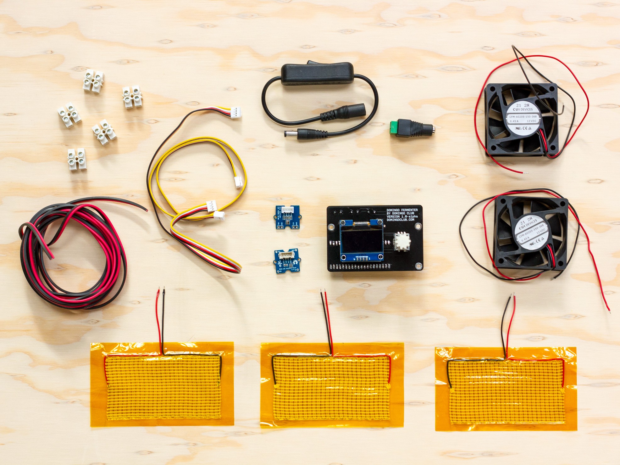


Components
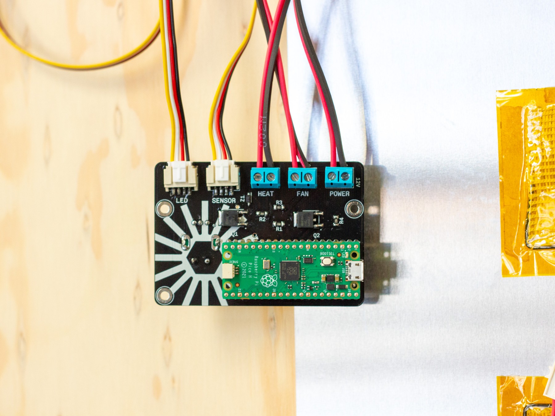
- Electronic Board
- Raspberry Pico pre-programmed
- OLED display
- Rotary encoder
- RGB LED, grove cable 40cm
- Temperature sensor DS18B20
- 3x Heating Pads
- 2x Fans
- Power connector
- Power switch
- 5x Terminal block
- Cable 20AWG 250cm
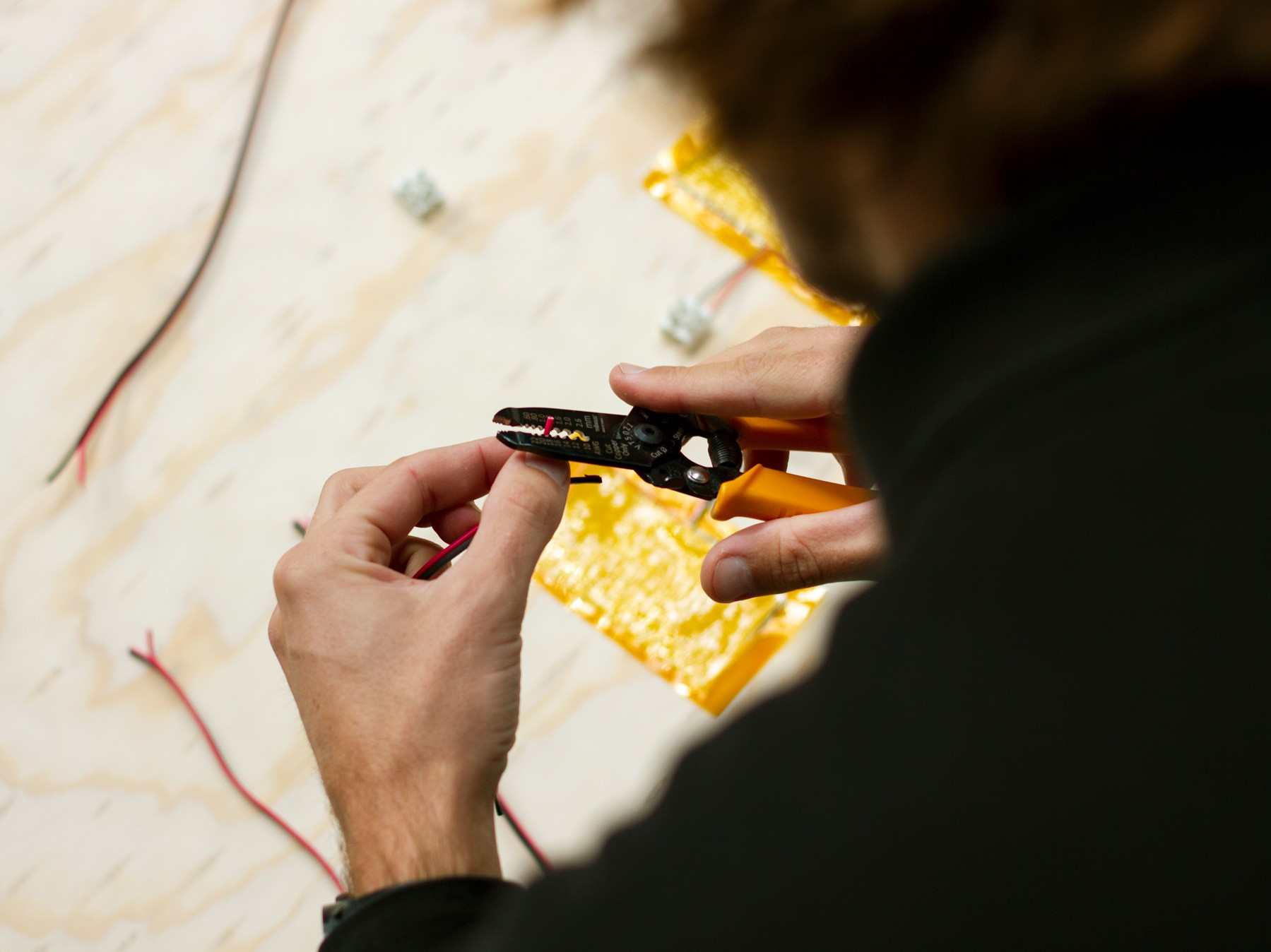
1. Preparing the cables
Cut the 250cm cable into 6 pieces according to the following measurements.
- 1x 60cm
- 3x 20cm
- 2x 65cm
Strip the end of each cable with a cable stripper or cutter.
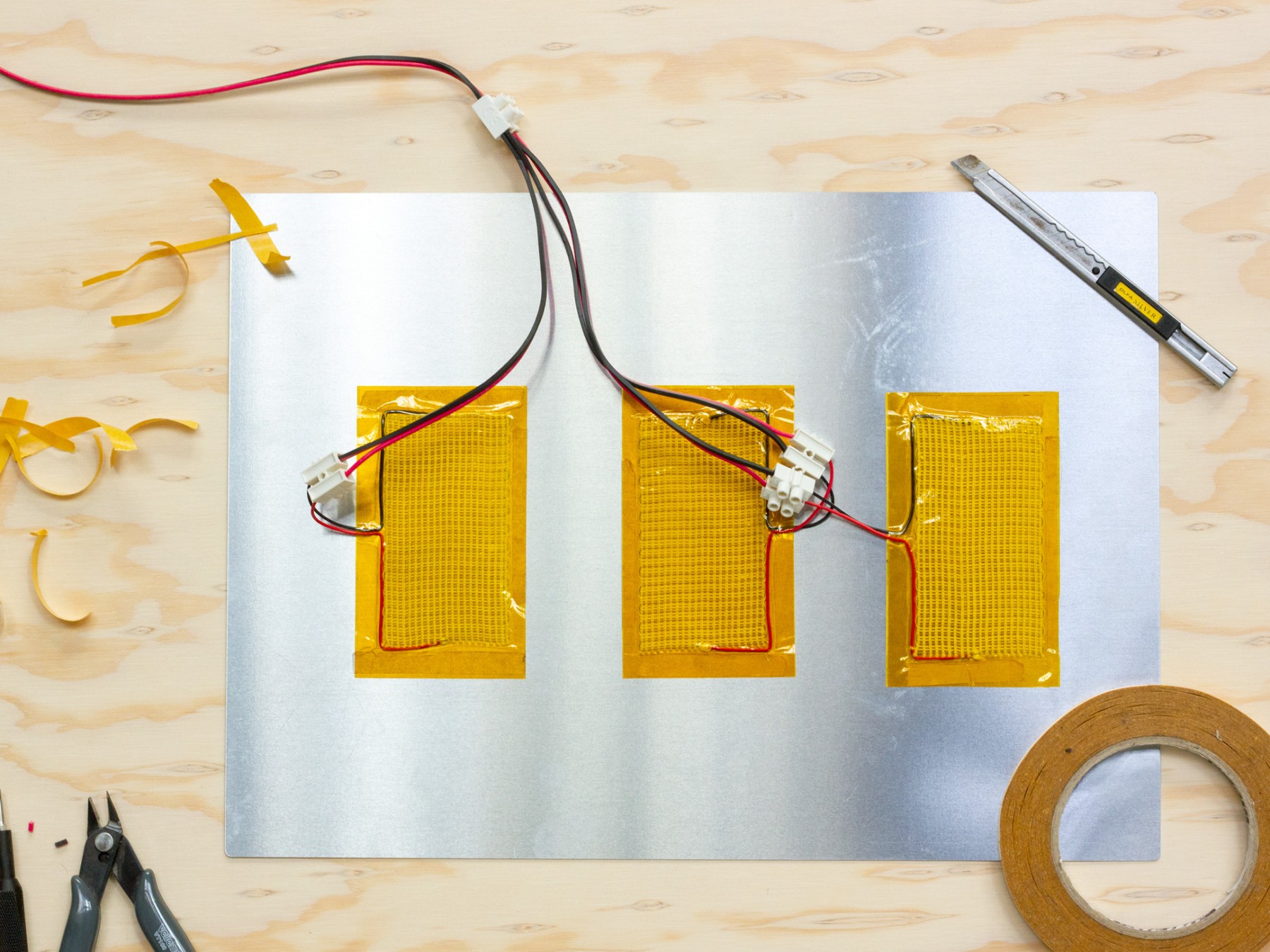
2. Connecting the heating pads
The three heating pads are connected together so that they have the same output from the PCB. To do this, connect each heating pad to a terminal block, then to a 20cm power cable. Then connect the three 20cm power cables (from each heating pad) to a single block, which should then be connected to a 65 cm cable that goes to the PCB.
We recommend that you then stick the heat pads, using double-sided tape, to a sheet of aluminium to ensure optimum heat diffusion.
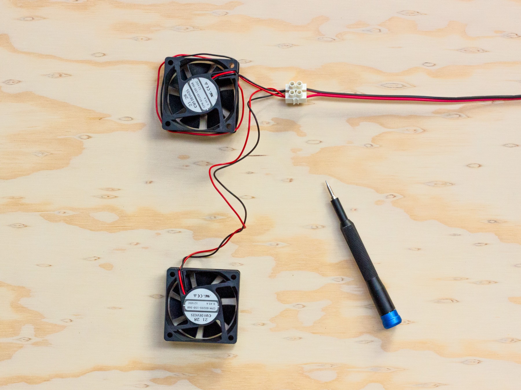
3. Connecting the fans
the fan connection follows the same logic as the heating pads. The cables from the two fans go to the same terminal block, which is connected to a 60cm cable, which then goes to the PCB.
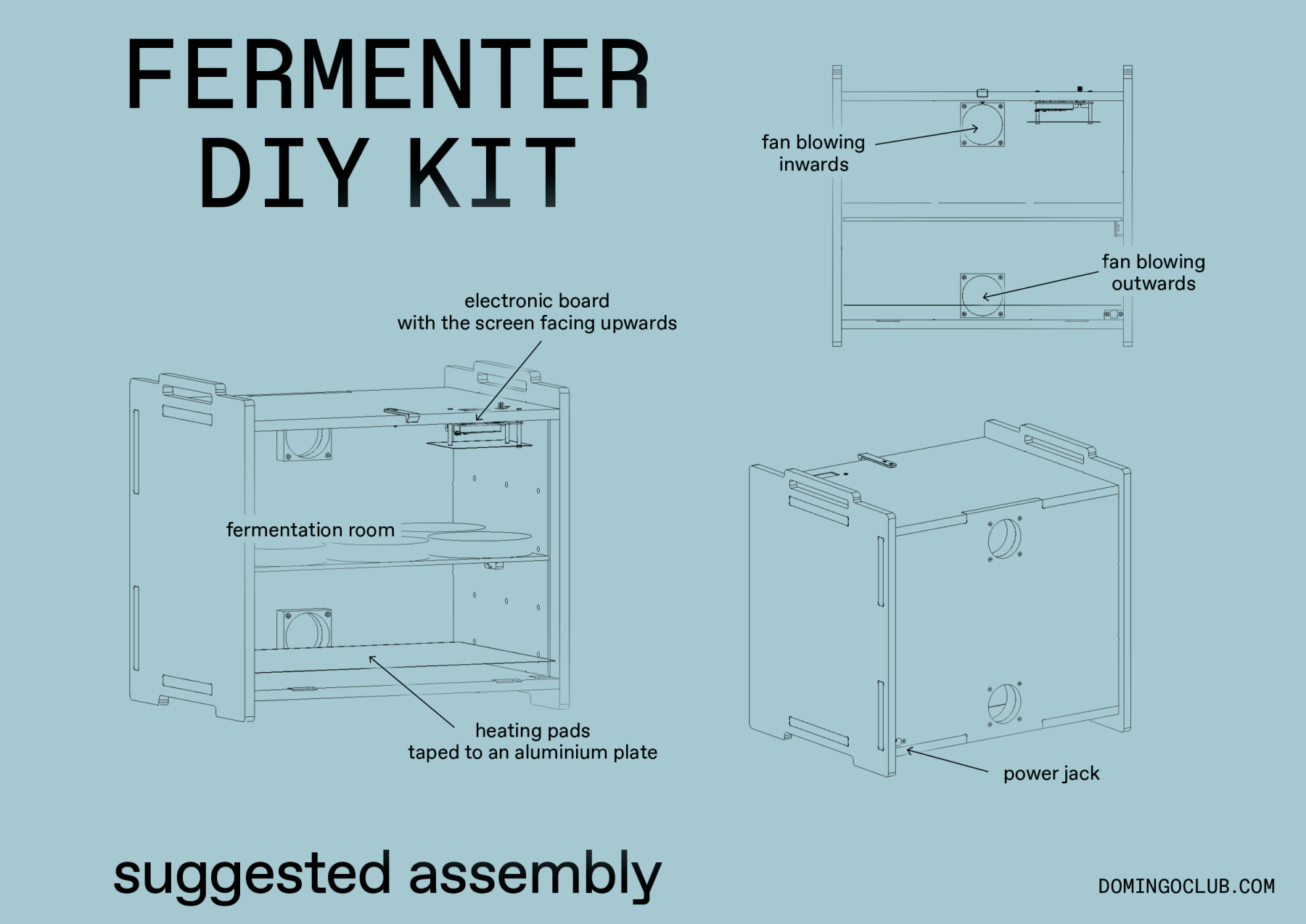
The fans will be placed in opposite directions so that the bottom fan blows from the outside towards the fermenter, and the top fan blows from the inside towards the outside. This ensures optimum air circulation.
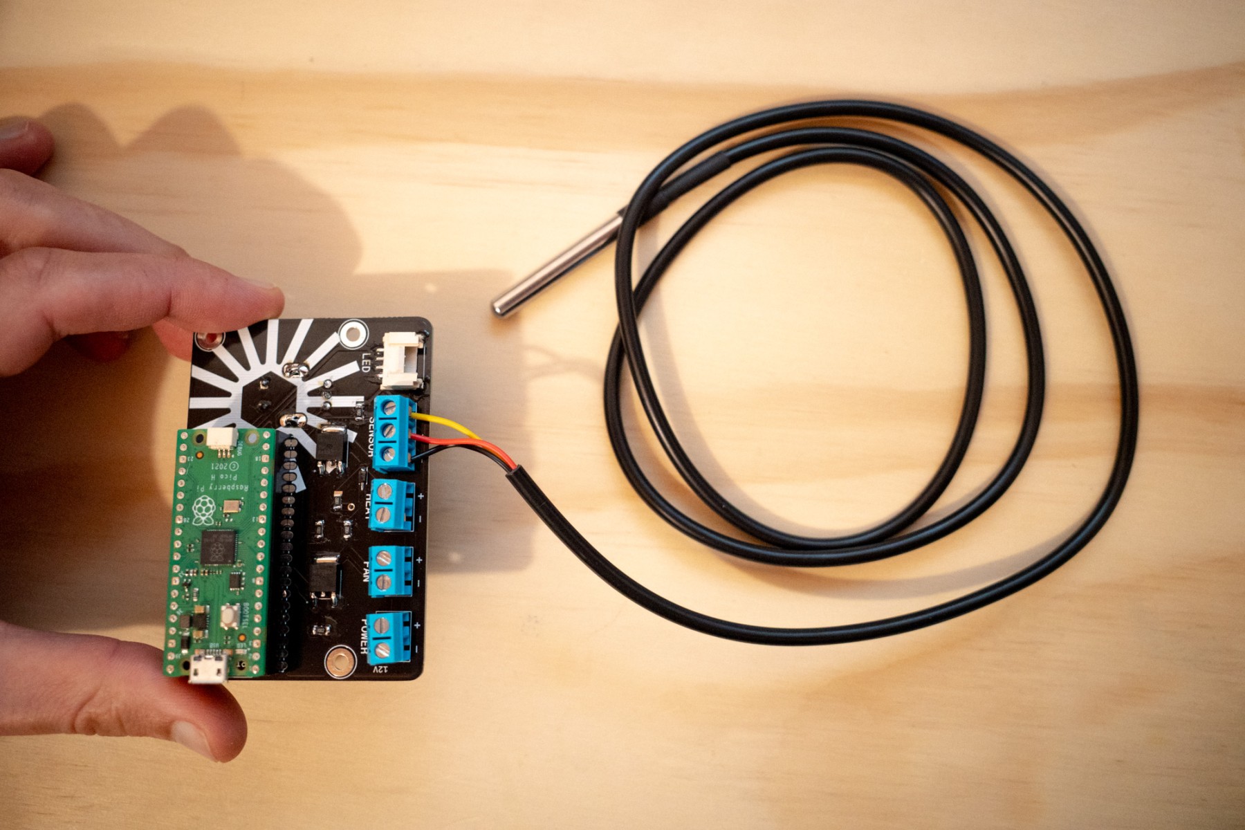
4. Connecting the sensor
The new version of the electronic kit includes a DS18B20 sensor that can be easily handled and even immersed in liquids to measure their temperature. Practical for measuring the temperature of rice during koji fermentation, for example. The sensor is connected using the three-position block terminal on the PCB.
5. Connecting the LED
The LED indicates the status of the fermenter, whether it is heating up, cooling down or at the right temperature. The LED clips into the grove connector on the PCB. To remove it, press lightly on the small flexible part of the connector.
6. Connecting the power
connect a 65cm cable from the power connector to the power input of the PCB.
To power the fermenter, we recommend a 12V 5A power supply of this type.
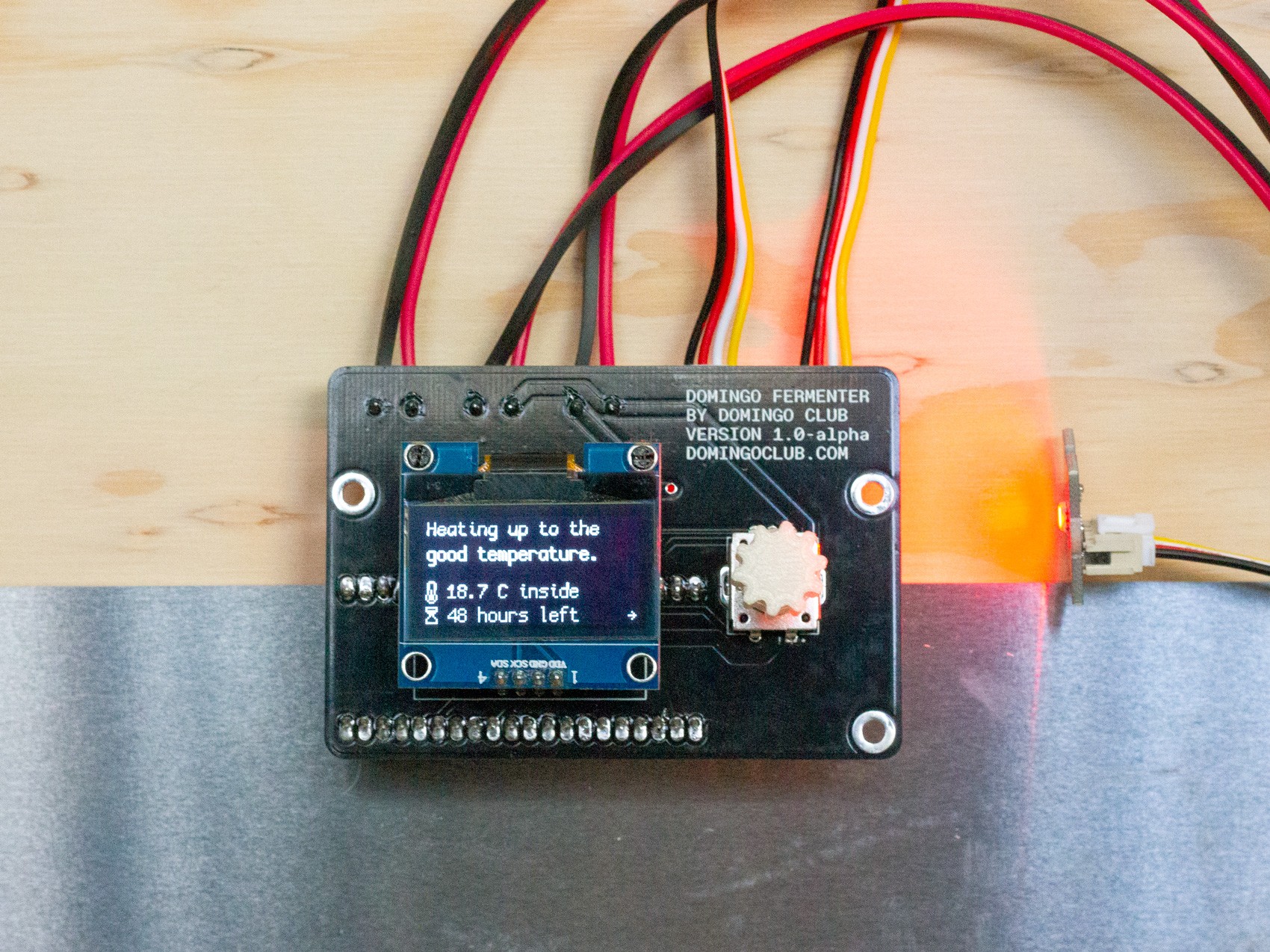
7. Checking that everything is working
Now that everything is connected, switch on the power supply and check that the PCB and its display light up correctly.
Select manual mode and check that the various components are operating correctly. If a temperature is visible, the sensor is working correctly. Touching the sensor for a few moments should cause the temperature reading to change. If you set the temperature warmer than the ambient temperature, the heating pads should start to heat up. If you request a temperature lower than the ambient air temperature, the fans should come on. The LED should change colour with each change in status.
Check your connections if anything goes wrong.
8. Placing the kit in a box
This drawing shows our recommendations for the placement of the elements in order to have an ideal temperature control system for fermentation.
Documentation in progress, visit us again soon.
Don’t hesitate to contact us if you have any questions.
License
Our designs use an open source licence CC BY-NC-SA 4.0 so anyone can download, improve, and change them to fit their particular needs.
Attribution
You must give appropriate credit, provide a link to the license, and indicate if changes were made. You may do so in any reasonable manner, but not in any way that suggests the licensor endorses you or your use.
NonCommercial
You may not use the material for commercial purposes.
ShareAlike
If you remix, transform, or build upon the material, you must distribute your contributions under the same license as the original.
No additional restrictions
You may not apply legal terms or technological measures that legally restrict others from doing anything the license permits.